A recent art project dealt with the application of switching loads on and off. These are in fact DC motors or cooling fans for practical terms. They were used in this installation.
Basically, what we wanted was to create a wind composition with these fans, by turning them on and off. The design has 3 groups of 5 cooling fans each. The idea is to control them, switching them on and off, with different combinations, so that the resultant direction and intensity of the wind creates the composition. This post depicts what the application was like, mentioning the materials, and procedure, with a little theory. In short, a microcontroller generates the control signals, later used by a set of transistors to switch the fans on and off. The speed of this switching translated into variation in voltage, i.e. variation in speed of the fan.
Well, in fact, Instead of only turning the fans on and off to compose with them, you can vary their speed, creating a smooth change on the transitions between levels of intensity of the fans.
To do so, I use a Microcontroller to produce the control signals. The chip is actually part of a platform similar to Arduino, named Pinguino. This is a development board that emerged after Arduino, and it is essentially the same, although Pinguino runs a Microchip’s PIC32 in it. I chose this platform due to my previous experience programming PICs and not Atmel´s, plus it’s cheaper.

Another factor is its architecture. Pinguino PIC32 OTG has a 32 bit MCU, and at the time of purchase it was easier to find than the Arduino Due, which is the first Arduino to have a 32 bit CPU. For this application in particular you would not need such a robust chip, but since I intend to stream audio with it, this power would come in handy in the future.
On the other hand, Pinguino is the unknown cousin of Arduino, it does not have all the documentation and community of the superstar. Nevertheless, the texts and program functions are growing. Its IDE is similar to that of Arduino and the programming is just as easy.
Now, back to the switching of the fans. To turn loads like these on and off, a microcontrollers output is not strong enough. A more powerful source is needed to feed them. So the chip will only do the task of deciding whether they are spinning or not.
To do this, a signal is sent to a transistor that will work as a switch. The load (fan) is connected to the Colletor in the transistor, fed from an external power source. The Base of the transistor is tied to the analogical output of the Pinguino, while the Emitter is grounded. A Schematic of the circuit is shown a couple of paragraphs below.
The analogical output is used for it actually produces a Pulse Width Modulation. This PWM switches the transistor on an off rapidly, allowing current to flow through the load intermittently. What this does is to produce an average DC voltage drop on the load that is relative to the duty cycle of the PWM. And a changing voltage on the motor is one of the ways in which its speed can be controlled.
Then it follows that, since the transistor is actually going to handle the current of not only one fan, but 5, it has to amplify to a satisfactory level. Since the current that it will amplify will be divided by five, it has tu surpass the nominal current of these fans by five times. Hence the device to be used is not a single NPN, but an array of two of them, the Darlington Transistor (a FZT605 Surface mount in this case), which has a larger gain. The expression that relates the gain with the configuration of the transistor is this:
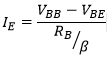
Ie is the current out of the Emitter, Vbb is the voltage applied to the Base, Vbe is the voltage drop between the Base and the Emmiter, 1.7 V for this Darlington, and Rb is the resistor into the Base, whilst β is the current gain. Experimentally, the gain for this Darlington showed to be around 3,000 depending on the voltages and currents applied.
The resistor tied to the Base of the Transistor will determine the current going into it. This, multiplied by the specific gain at the particular operating rates will let you know the current at the Emitter (and the Collector). In this case 470 Ω is enough to amplify up to a current that exceeds by a safe margin the required flow tu run 5 fans. This is the circuit used:

This cooling fans have a specification of 12 V and 0.43 A. So the current needed is of 5 x 0.43 = 2.15 Amps. This means that the Transistor has to be capable of maintaining such currents. In practice, these fans would drag up to only 0.38 A, requiring from the Transistor to deliver a bit less current. However, this flow of electric charge proved to generate too much heat.
In subsequent revisions of the design, heat sinks are to be used, else the loads should be distributed among more transistors. Nevertheless, this design worked well on an installation that lasted 4 days, with a program that would never run the loads at 100% of its capacity for longer than a few seconds, giving time for the heat not to accumulate so catastrophically.
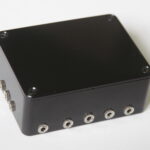
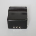
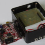
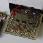
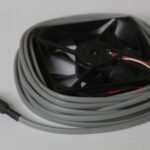
The final outcome of this circuitry was a black box, with 15, 3.5 mm mono audio plugs, which are used to connect the fans into the circuit and switch them accordingly. Again, the application of this circuit is this project (Weather Series – Wind).
Photos of the circuit, the resultant PCB and the black box are shown in the next gallery: