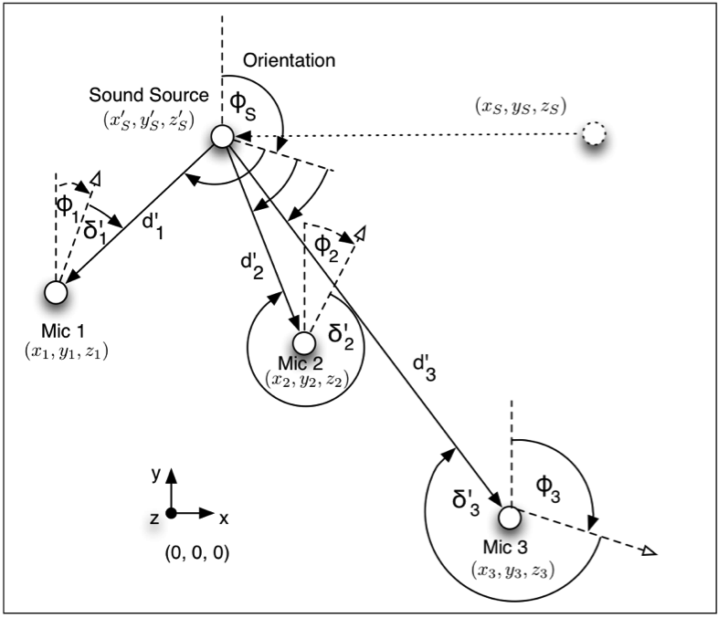
As said before, a virtual space is created within the computer; a virtual sound source is placed on it and several microphones as well. A reference coordinates system is stated in order to measure the distance of microphones/speakers and sound source(s) in relation to the listener, so that this distance is accounted to calculate the sound pressure decay at each of the virtual microphones and the time sound takes to arrive at them (delay). As shown in the next figure, the coordinates can be used with Cartesian of polar notation:

The expression to calculate the gain decrease was presented before, but is shown again for practicality. It and the expression to get the time delay considering both the position of the sound source and the listener are as follows:
time delay (Braasch, Peters, & Valente, 2008 )where Cs stands for the speed of sound, using 344 m/s as the accepted standard, and
gain in function of distance. (Peters, Matthews, Braasch, & Stephen, 2008) In which the gain gi is calculated using the distance previously obtained from the model, and the exponent q, that increases the effect of distance in the gain decrease.
On top of this analysis, an important feature is added to this technique; that is the effect of microphones’ directionality, which is attributed to the virtual microphones on the Auditory Virtual Environment (AVE) (Braasch, Peters, & Valente, 2008). This directionality adds a more robust simulation of the sound as well as an enhanced flexibility of the system as it enables it to locate and orientate the microphones on any fashion, according to the sound that is created.
The virtual directivity performs an improvement from real situations in which even Omni directional microphones have a slight frequency response for higher tones, so perfect behaviour can be created. Also, unwanted frequency responses are avoided, as there is none in this directivity modelling. This virtual directivity is expressed as
Virtual microphone directivity (Peters, Matthews, Braasch, & Stephen, 2008) which is in function of the angle from which the sound is arriving at the virtual microphone, as shown on the previous figure. The a and b coefficients are taken from the following table, that provides the value for the different types of microphones

where a and b are normalized to 1 and work with the angle from which the sound is approaching. For further roughness of the attenuation effect, the w coefficient is added to the expression.
Therefore, the final gain at every microphone/speaker, with the corresponding attenuation from the directivity model and the distance effect is given by
gain attenuation with directivity included. (Braasch, Peters, & Valente, 2008) where gd is the gain from the distance measurement.
Finally, if we take the virtual sound source signal to be x(t), the signal arriving at the microphone/speaker after a time t to be x(t-t), and the signal at the microphone itself to be y(t) , we can express this later as
sound at the microphone/speaker (Braasch, Peters, & Valente, 2008) using all of the variables previously mentioned. This will yield to a signal delayed and attenuated in relation to the distance and location of sources and microphones/speakers.
Adding directionality to the sources themselves can do further modelling, so that the illusion of location can be better produced in a more immersive and realistic fashion. (Peters, Doctoral Thesis, 2010)
…
Further on this chapter:
0. CONTENT
2.1 SONIFICATION
2.1.1 SONIFICATION DEFINITIONS AND CONCEPTS
2.2 SPATIALIZATION
2.2.1 ACOUSTICS INVOLVED IN SPATIALIZATION
2.2.1.1 COORDINATES SYSTEM
2.2.1.2 DELAY AND GAIN
2.2.1.3 REFLECTIONS
2.2.1.4 SOUND ACQUIREMENT
2.2.2 SPATIALIZATION TECHNIQUES
2.2.2.1 ViMiC
2.2.2.1.1 BASIC FUNCTIONING
2.2.2.2 JAMOMA
2.2.2.2.1 VIMIC MODULES
2.2.2.2.2 OUTPUT MODULES


