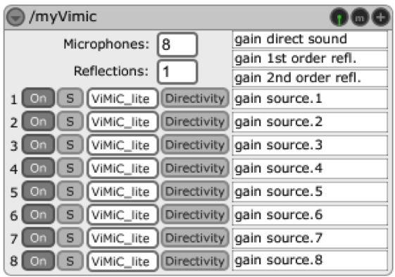
More of the Jamoma modules and their functionality and specifications can be found in the manual (Peters, ViMiC, 2009) and at (Jamoma, 2011). Within the Jamoma’s ViMiC bundle there is a module to spatialize a single sound source and a version of the same one that uses Max/MSP’s polyphony tools to render 3D audio of up to 8 sources. This later is the one used for the current project; it is depicted on figure 8.
Figure 8. Vimic8~ module used on the patch.
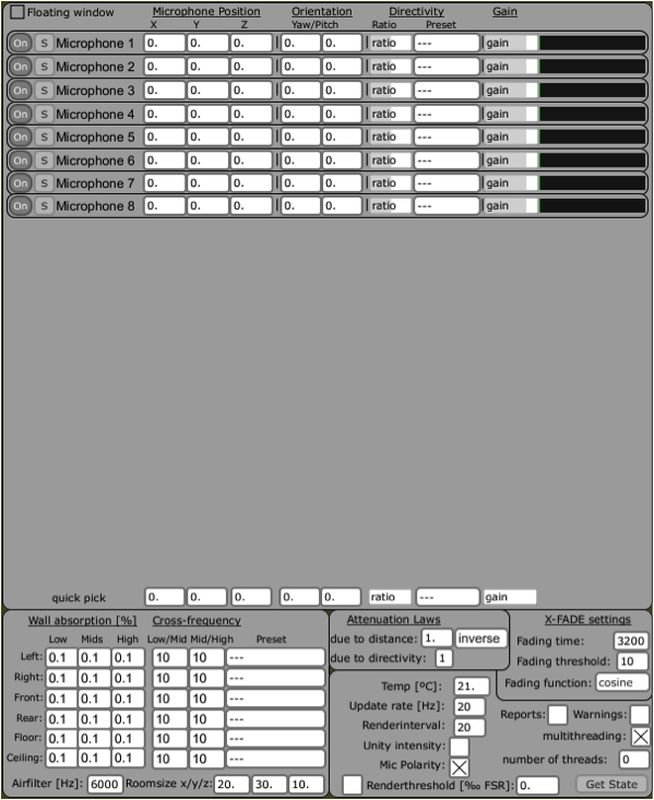
On it the number of virtual microphones can be set, altogether with the type and number of rendered reflections, the type and gain of the sound sources, plus there are controls for muting and turning on/off the whole module and the sources separately. The controls at the top right serve to bypass the sound and bring up another window that contains more configurable information about the system such as the position of microphones, size and characteristics of the virtual room created and so on; it is shown on the following figure.
The module has 9 inlets and 2 outlets. The leftmost inlet receives OSC messages that modify parameters like the sounds’ position on space, their gain, reverb settings, master gain, render method and interval, directivity of microphones and physical attributes of the model.
The rest of the inlets, numbered from left to right, admit each of the eight signals feeding the system that will later spatialize them. Each one of them has a simple interface control as seen before.
With respect to the outlets, the leftmost one delivers OSC messages whereas the right hand side port expels a single thread containing multichannel information that must be read by a decoupling module or patch.
Figure 9 shows the inspector (name given to control windows for MAX/MSP objects) of Jamoma’s ViMiC module. On it the positions of the speakers/microphones must be set, in order to get the module to calculate the delays and gains at each one of them. The virtual directionality of these microphones is also set in this inspector.
Further control is obtained by setting the size of the room, its reflective properties given by the walls’ absorption coefficients. Even physical attributes of the environment can be changed, such as the room temperature, which would change the speed of sound. The frequency with which the system updates its rendering is also modifiable, altogether with the fading curves for moving sounds and microphones polarity and orientation, these later useful to avoid clips when the position of the sources changes discretely.
Figure 9. Inspector of the ViMiC module
As we know from the Doppler effect theory, when a source of sound is moving in space, the change on the distance to the listener affects the perception of the sound waves, changing the tone or frequency that is effectively perceived. As the natural effect it is, it adds a realistic feature to the synthesized sound. Sound can be localized and moved through the virtual space with and without the rendering of Doppler effect using ViMiC module, which uses a delay line interpolation technique (Peters, ViMiC, 2009). It is a matter of changing the render mode on the main module, shown in figure 9. The default rendering mode is ViMiC_lite, which renders Doppler with simplified room acoustics, making it less heavy to process.
…
Further on this chapter:
0. CONTENT
2.1 SONIFICATION
2.1.1 SONIFICATION DEFINITIONS AND CONCEPTS
2.2 SPATIALIZATION
2.2.1 ACOUSTICS INVOLVED IN SPATIALIZATION
2.2.1.1 COORDINATES SYSTEM
2.2.1.2 DELAY AND GAIN
2.2.1.3 REFLECTIONS
2.2.1.4 SOUND ACQUIREMENT
2.2.2 SPATIALIZATION TECHNIQUES
2.2.2.1 ViMiC
2.2.2.1.1 BASIC FUNCTIONING
2.2.2.2 JAMOMA
2.2.2.2.1 VIMIC MODULES
2.2.2.2.2 OUTPUT MODULES

