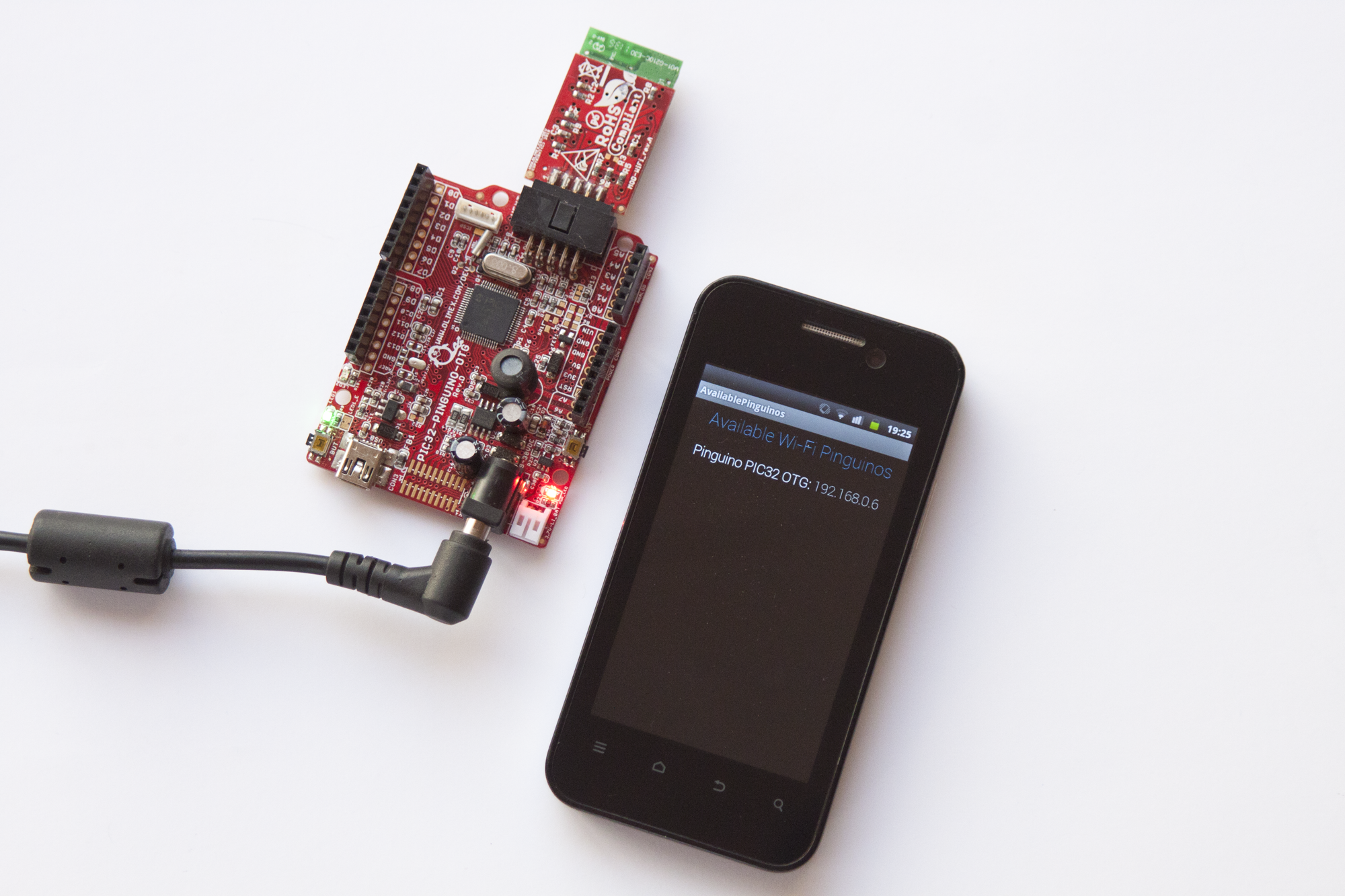
This new version of the Pinguino Control project makes possible Wi-Fi control of a Pinguino Development board (it uses a PIC32) from and Android device. The project takes advantage of the Wi-Fi capabilities the MOD-WIFI module provides. Unlike the previous version of the project, this one does not need to connect to a computer and then to Pinguino.
Get the App:
Get the Firmware:
The MOD-WIFI module can be obtained from Olimex. It contains Microchip’s low power RF module MRF24WB0MA that enables Wi-Fi communication when connected to a Pinguino board using the UEXT interface. This turns Pinguino development boards into complete wireless platforms.
Same as the previous version of Pinguino Control, this new one allows setting of pin states (i.e. Input, Output, Low, High), plus monitoring of Analogue Inputs and control of Analogue Outputs. These Analogue Outputs are in fact accomplished by a PWM peripheral function embedded in the Microcontroller.
Simply download the Android application from Play Store, and select the model of communication with Pinguino, either Wi-Fi or USB.
In the microcontroller side of things, you need to program it with the correct firmware, plus changes in 2 lines of code, explained a bit later. There are two firmware versions. The first one, the previous, allows the microcontroller to receive data over CDC USB, whereas the second one is optimized to receive control messages over Wi-Fi by using the MOD-WIFI.
Both firmware versions are available to download from the link provided here, the same is with the complete code for the Android application.
Inside the folders of the project provided you will be able to easily identify which firmware code performs each function.
To use the control over Wi-Fi with Android it is necessary to change the SSID, or name, and the Password of the WLAN in the Pinguino’s firmware, for it to be able to connect to the network:
- Open the WF_Config.h file found in \PinguinoControl Release – v2_0\Firmware\WiFi\PIC32 MPLABX Project\Demo App – Pinguino Control V2-0\
- Modify line 118 and change “YOUR_SSID_NAME” for your own network name.
- Modify line 232 and change “YOUR_PSK_PHRASE” for your own network password.
After that, compile and program the microcontroller. Running it and using a MOD-WIFI the development board will automatically start, connect to the network and start broadcasting its own IP address, altogether with the name of the board. Android will then receive this IP and name and display them in the list of available wireless Pinguinos. Click on such name to establish the connection and start controlling the microcontroller.
If Wi-Fi communication is selected in the Android app, it is assumed that a MOD-WIFI is connected to Pinguino. To control such module, Pinguino uses 5 pins that cannot therefore be used for custom control. These pins are A4, A5, D11, D12 and D13. In the Android application the control of these pins is disabled when on Wi-Fi mode. The Android device and Pinguino must be under the same WLAN.
If USB communication is selected in Android, it is assumed that the messages are sent to a computer, which is running a Pure Data patch that is also provided in the project folder. The patch only receives the messages and resends them over USB to the microcontroller. Care must be taken on the port number and IP addresses. There is also an equivalent patch, but for Max MSP.
More documentation about the format of the control messages in the communication protocol is found in the excel file included in the link as well. There is also more information about version 1.0 of the project in the previous entry of this website.
Have happy programming, controlling, applying and creating. Please use and abuse this material to find bugs and further develop it.
Cheers.


1 thought on “Pinguino Control – WiFi”
Comments are closed.